Skip to content


Cutting thick technical foam for custom shadow boards, protective flight cases, thermal insulation, or orthotic insoles should be straightforward. Yet production managers frequently confront three frustrating bottlenecks: a pronounced V-shaped cut taper on blocks thicker than 15 mm, sunken concave sidewalls caused by uncontrolled heat buildup, and sticky, re-solidified melted slag along bottom corners. Traditional knife plotters distort cellular geometry under mechanical blade drag, while steel-rule die tooling requires days of turnaround and thousands of dollars in tooling costs for every design change.
Engineering Definition:
CO₂ laser foam cutting is a non-contact sublimation and thermal ablation process at a 10.6 µm optical wavelength, utilizing an extended Rayleigh-length optical lens (typically 3.0 to 4.0 inches) and low-pressure laminar coaxial air assist to vaporize cellular polymers (EVA, EPE, and Polyurethane) with vertical edge perpendicularity, zero mechanical compression, and millimetric contour precision.
When engineered with appropriate focal optics and thermal management, an industrial CO2 laser cutting machine processes single prototypes or multi-thousand foam inserts with identical repeatability. Below is the comprehensive technical breakdown of polymer thermodynamics, optical calibration, empirical parameters, and shop-floor protocols to produce clean, vertical cuts across closed-cell and open-cell foams.
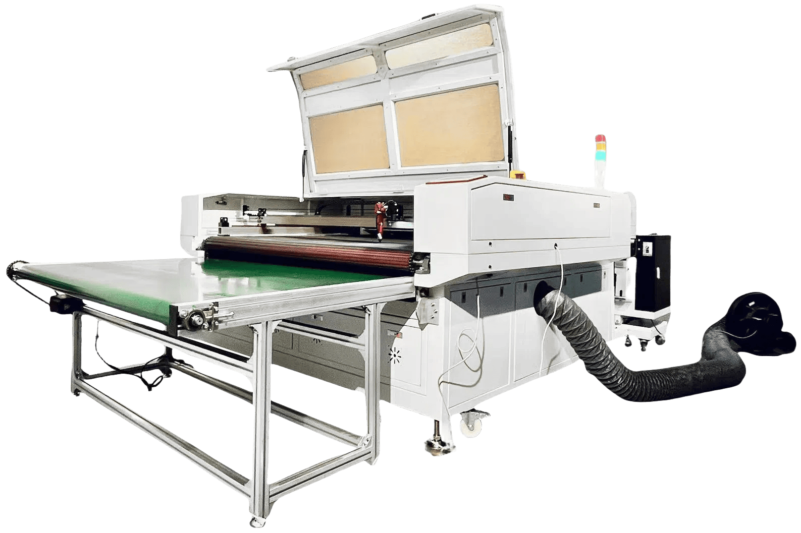
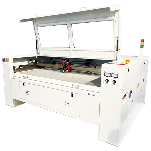
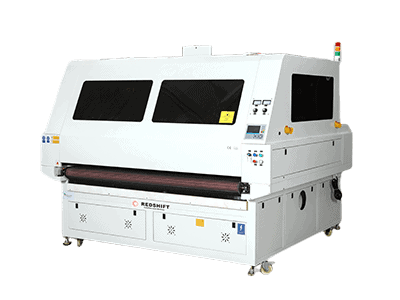
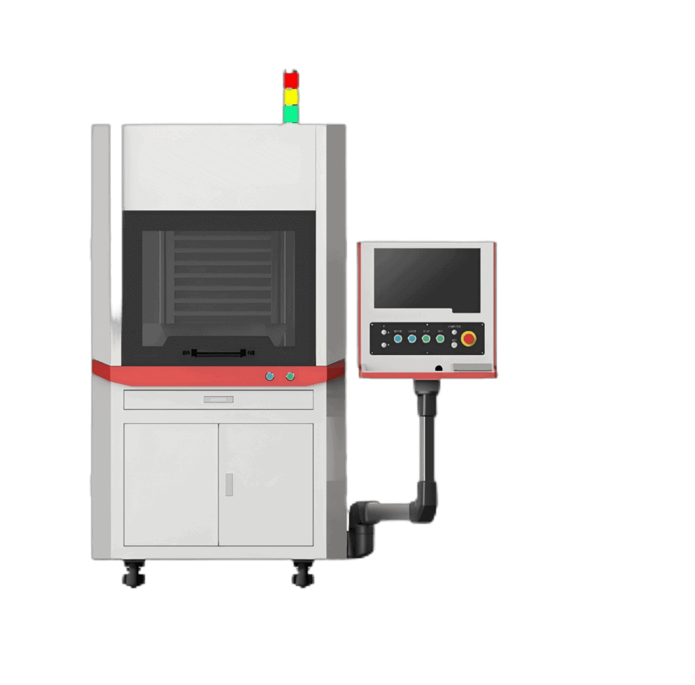
Stop blade dragging and edge taper issues on technical foam and roll stock. Discover our RedShift CO₂ Laser Cutter with Conveyor & Collection Table—engineered with automated unwinding, continuous conveyor feed, and high-pressure coaxial air assist for vertical edges and zero taper on EVA, EPE, and polyurethane foam.
Cellular Polymer Chemistry: Cutting EVA, EPE, and Polyurethane Foam
The cellular structure, blowing agent, and polymer backbone determine how foam absorbs 10.6 µm optical radiation. Treating all foams identically causes severe scorching or incomplete separation.

1. EVA Foam (Ethylene-Vinyl Acetate)
EVA is a copolymer with a closed-cell matrix, widely utilized in tool organizers, high-end packaging, protective sports pads, and cosplay fabrication.
- Thermal Response: Under the laser beam, EVA transitions cleanly from solid to volatile gas with minimal liquid melt phase.
- Edge Quality: Produces a firm, smooth, slightly sealed sidewall with excellent tactile feel.
- Density Range: Typically processed from 38 kg/m³ (soft packaging) up to 200 kg/m³ (rigid tool trays). Higher densities require proportionately slower cutting speeds but yield exceptionally crisp vertical edges.
2. EPE Foam (Expanded Polyethylene / Pearl Cotton)
EPE is a lightweight, resilient, non-crosslinked closed-cell foam widely deployed for electronic shock protection.
- Thermal Response: Low melting temperature (approx. 105°C to 115°C). The cell walls readily collapse if optical dwell time is excessive.
- Cutting Characteristic: Requires high cut speeds and high laser wattage (e.g., 150W to 300W). If cut too slowly, the localized heat melts adjacent micro-cells, producing an uneven, scalloped kerf.
3. Polyurethane (PU) Foam (Polyester & Polyether)
PU foams are predominantly open-cell matrices ranging from acoustic egg-crate foam to rigid insulation blocks.
- Thermal Response: Polyurethane undergoes rapid thermal degradation. Open-cell structures allow laser energy to penetrate slightly deeper into pore openings.
- Edge Quality: Cuts cleanly with zero stickiness. However, combustion produces higher particulate volume and isocyanate vapors, demanding robust fume evacuation.
4. Forbidden Polymer Warning: PVC-Based Foams
Never process expanded PVC boards (e.g., Sintra, Komatex) in a laser cutter. Thermal breakdown of polyvinyl chloride releases gaseous hydrogen chloride (HCl), which instantly corrodes linear rails, optical coatings, and ball screws, while creating severe respiratory hazards for shop personnel.
The Optical Principle: How Longer Focal Length Helps Reduce Edge Taper in Thick Foam
The primary challenge in laser cutting 20 mm to 50 mm cellular polymers is sidewall taper (the V-shaped or hourglass bevel). This profile is fundamentally influenced by Gaussian beam propagation dynamics, though the final cut edge is also shaped by material thermal conductivity, cutting speed, and air assist.
Understanding the Rayleigh Length and Depth of Focus
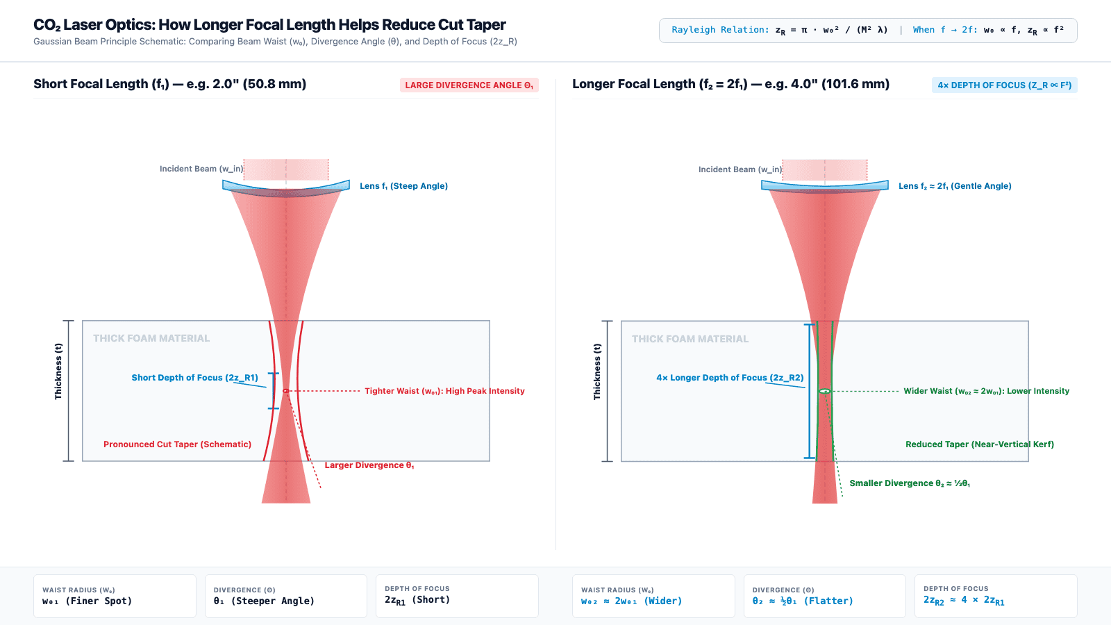
In Gaussian beam optics, a focused laser beam converges to a minimum beam waist radius (w0) and then diverges. The Rayleigh length (zR) is the distance along the propagation axis over which the beam cross-sectional area doubles (or beam radius increases by a factor of √2):
Gaussian Beam Formula: zR = π · w02 / (M2 · λ)
Where w0 is the waist radius, λ is the 10.6 µm CO₂ laser wavelength, and M2 ≥ 1 represents beam quality. The total effective depth of focus is conventionally defined as 2zR.
For a collimated incident beam of diameter D, the waist radius and Rayleigh length scale with lens focal length f:
w0 ∝ f, zR ∝ f2, θ ∝ 1/f
- Short Focal Length Lens (e.g., 2.0" / 50.8 mm): Produces a tighter focal spot (w0) and high peak irradiance, which is optimal for thin-sheet engraving. However, its convergence and divergence half-angles (θ) are steep, and its depth of focus (2zR) is short. Through thick foam (30 mm to 50 mm), the beam expands rapidly past the waist, causing an exaggerated cut kerf taper and bottom scorch marks.
- Longer Focal Length Lens (e.g., 4.0" / 101.6 mm): Doubling the focal length doubles the waist radius (w0) and quadruples the depth of focus (2zR ∝ f²), while cutting the beam divergence half-angle in half (θ ∝ 1/f). Although peak irradiance is lower, the optical beam waist remains slender and quasi-collimated across a much longer propagation span, dramatically reducing sidewall taper in low-temperature sublimation materials like EVA and PU foam.
Strategic Focus Sinking Protocol
Because Gaussian beams diverge symmetrically on both sides of the waist, never position the focal plane on the top surface of thick foam. Positioning focus on the top surface forces 100% of the material thickness into the diverging half of the beam.
Instead, sink the focal plane 35% to 50% into the depth of the sheet (e.g., set focus 12 mm to 16 mm beneath the top surface for a 35 mm slab). This distributes the converging and diverging beam profiles equally between the upper and lower surfaces, equalizing top and bottom kerf widths and minimizing unilateral draft angles. Actual edge squareness also requires balancing cutting speed, downdraft suction, and low-pressure coaxial air assist.
Empirical Parameter Matrix for 5mm to 50mm Foam
The following parameters represent baseline production data derived from calibrated industrial CO₂ flatbed systems equipped with high-voltage glass CO₂ laser tubes or RF metal ceramic tubes, utilizing dry coaxial air assist:
| Material Type | Thickness | Lens Size | Focus Position | Power (W) | Speed (mm/s) | Air (Bar) | Edge Tolerance |
|---|---|---|---|---|---|---|---|
| High-Density EVA (100 kg/m³) | 5 mm | 2.0" / 2.5" | Top (0 mm) | 60 W | 45–60 mm/s | 0.8 Bar | ±0.2° (Vertical) |
| Packaging EVA (45 kg/m³) | 10 mm | 2.5" | -3 mm | 80 W | 35–45 mm/s | 1.0 Bar | ±0.3° (Vertical) |
| Packaging EVA (45 kg/m³) | 20 mm | 3.0" / 4.0" | -8 mm | 100 W | 22–30 mm/s | 1.2 Bar | ±0.5° (Near-vertical) |
| Packaging EVA (45 kg/m³) | 30 mm | 4.0" | -12 mm | 130 W | 14–18 mm/s | 1.2 Bar | ±0.8° (Clean edge) |
| Dense Tool EVA (80 kg/m³) | 40 mm | 4.0" | -16 mm | 150 W | 8–12 mm/s | 1.5 Bar | ±1.0° (Clean edge) |
| EPE Pearl Cotton | 20 mm | 3.0" / 4.0" | -8 mm | 100 W | 30–45 mm/s | 1.0 Bar | ±0.7° (No cell collapse) |
| EPE Pearl Cotton | 40 mm | 4.0" | -18 mm | 250–300 W | 25–35 mm/s | 1.5 Bar | ±1.0° (High-speed fly cut) |
| Open-Cell PU Sponge | 25 mm | 3.0" | -10 mm | 80 W | 40–55 mm/s | 0.8 Bar | ±0.4° (Crisp pores) |
| Rigid PU Insulation | 50 mm | 4.0" | -22 mm | 150 W | 10–14 mm/s | 1.5 Bar | ±1.2° (Square kerf) |
Note: For thicknesses exceeding 30 mm, clean, moisture-free compressed air or nitrogen is recommended to prevent thermal flashovers. Operators should run incremental test cuts to compensate for material density variances.
Thermal Management: Mitigating Heat Shrinkage and Air-Assist Pressure
Achieving tight dimensional tolerance on custom packaging inserts requires mastering three secondary variables: bed support architecture, air-assist aerodynamics, and kerf compensation.

1. Bed Architecture: Knife-Strip vs. Honeycomb
Never place thick foam sheets directly onto a dense aluminum honeycomb table. When the high-power beam penetrates the bottom of the foam, the laser energy reflects off the honeycomb cell edges back into the bottom surface of the material. This creates melted burn indentations (flashback grid marks) and trapped slag.
The Solution: Always use an anodized aluminum knife-strip (slat) cutting bed with wide blade spacing (50 mm to 80 mm). For small, delicate foam cutouts that might fall through slats, elevate the sheet 20 mm off the bed using sacrificial pin supports.
2. Air-Assist Aerodynamics: Volume vs. Pressure
Air assist in foam cutting serves a distinct purpose compared to metal or wood processing.
- The Pitfall: Excessive air pressure (>2.5 Bar) acts like an air chisel, blowing molten polymer into neighboring porous cells and collapsing adjacent foam structures.
- The Best Practice: Use a wide-aperture nozzle (2.5 mm to 3.0 mm diameter) with steady, moderate pressure (1.0 to 1.5 Bar). The objective is to gently purge vaporized polymer out through the kerf before it condenses, without deforming the semi-molten sidewalls.
3. Kerf Offset and Clearance Tolerances
Because the laser beam has a physical width, cutting exactly on CAD vector lines will result in pockets that are slightly oversized (and cutout inserts that are slightly undersized).
- Measured Kerf Width: Ranges from 0.35 mm on 5 mm EVA to 0.75 mm on 40 mm foam cut with a 4.0-inch lens.
- Software Offset Rule: Apply a Kerf Compensation (Outward Offset) of +0.20 mm to +0.35 mm on male inserts, or -0.20 mm to -0.35 mm on female pocket cavities in your CAM software (e.g., LightBurn, RDWorks). This ensures a snug, zero-play friction fit for precision tools and electronic equipment.
Comprehensive Tooling Comparison: Laser Cutting vs. CNC Knife vs. Die Cutting
Selecting the correct production methodology depends on batch volume, thickness, and contour complexity. The table below provides an objective comparison of technologies competing in modern packaging and upholstery facilities:
| Production Parameter | Industrial CO₂ Laser Cutter | CNC Digital Oscillating Knife | Hydraulic Steel-Rule Die Cutting |
|---|---|---|---|
| Tooling & Setup Cost | $0 (Direct CAD-to-Cut) | $0 (Direct CAD-to-Cut) | $300 to $2,500 per die set |
| Design Changeover Time | Instant (Seconds) | Instant (Seconds) | 3 to 7 business days |
| Max Material Thickness | Up to 60 mm (with 4" optics) | Up to 45 mm (blade length limited) | Up to 25 mm (tends to crush edges) |
| Small Feature / Tight Radii | Sub-millimeter (0.5 mm radius) | Limited by blade width (min 3–5 mm) | Limited by bend radius of steel rule |
| Complex Finger Slots | Effortless (No blade binding) | Difficult on tight pocket corners | Requires specialized ejection rubber |
| Mechanical Edge Distortion | Zero (Non-contact beam) | Slight blade drag on soft low-density foam | Severe edge bevel & inward compression |
| Material Versatility | Closed & open cell foams, acrylic, wood | Foams, rubber, corrugated cardboard | Thin foams, gaskets, paper, felt |
| Disadvantages & Limits | Fume exhaust required; slight thermal edge | Blade wear on abrasive foams; slower travel | High tooling cost; impractical for prototypes |
| Ideal Production Run | 1 to 5,000 units / High complexity | 1 to 500 units / Low contour detail | 10,000+ units / High-volume identical shapes |
Environmental Safety: Fume Evacuation and Active Fire Prevention
Porous polymers trap high volumes of atmospheric air within their cellular matrices. When heated by a concentrated infrared laser beam, improper evacuation can lead to fire hazards or noxious shop emissions.
1. Fume Exhaust Volume and Static Pressure
Open-cell and closed-cell foams generate significant smoke volumes composed of micro-particulates, hydrocarbons, and organic compounds.
- Ensure a dedicated centrifugal exhaust blower delivering a minimum of 1,200 to 1,800 m³/h (700 to 1,050 CFM).
- Utilize dual-duct draft extraction: high-velocity downdraft under the knife-strip bed pulls heavy residues downward, while top-hood draft captures rising vapor plumes.
- Where external roof venting is restricted by local environmental ordinances, pair the machine with an industrial multi-stage fume filtration unit equipped with spark arrestors, M6 pre-filters, HEPA H14 filters, and a deep activated carbon chemical adsorption bed.
2. Fire Prevention Protocols
- Air Assist Interlock: Never fire the laser tube without positive air pressure confirmed at the cutting nozzle. Coaxial air continuously quenches ignition-phase micro-flames at the vapor front.
- Pre-Set Travel Vectors: Program lead-in and lead-out paths outside the critical perimeter to prevent beam dwell dwell marks.
- Never Leave the Machine Unattended: Always maintain a designated, trained operator equipped with a Class CO₂ or clean-agent fire extinguisher within reach during thick foam operations.
Industrial Equipment Configurations & Factory Verification
To process full 1,000 × 2,000 mm or 1,300 × 2,500 mm raw foam billets efficiently, standard desktop or hobbyist enclosures are insufficient. High-capacity contract manufacturers require purpose-built industrial hardware:
- Motorized Z-Axis Travel (≥200 mm Clearance): Accommodates thick multi-layer foam slabs and custom clamping jigs without removing the cutting table.
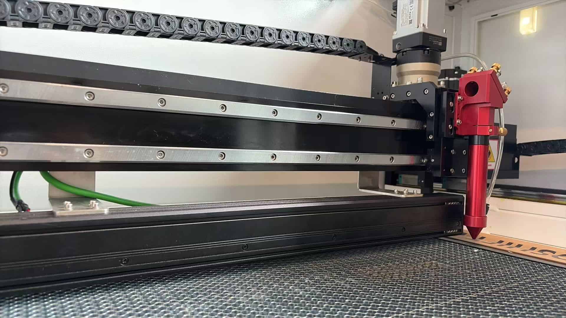
- Dedicated Long-Focal Optics Tube: Accommodates 3.0" and 4.0" focal lenses with calibrated nozzle extensions to maintain constant 2 mm to 3 mm standoff distance from the material top surface.
- European Regulatory Compliance: Look for complete CE declaration, dual-channel safety interlocks, emergency stop circuits, and Class 4 certified protective optical enclosures.

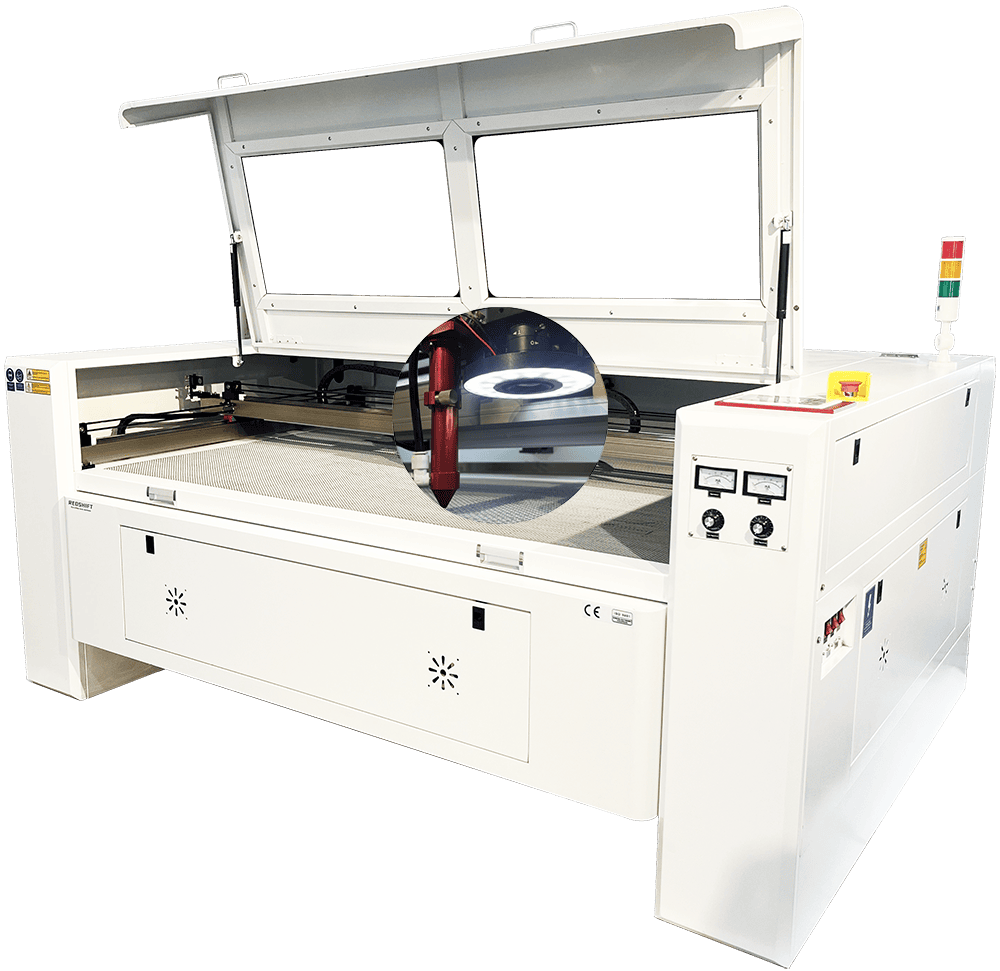
Eliminate cut taper: Scale your protective packaging, tool shadow boards, and orthotic foam fabrication with high-clearance motorized Z-tables, 4.0" telecentric optics, and high-flow downdraft extraction.
- Working Bed Sizes: 1300x900mm / 1600x1000mm / 1300x2500mm formats
- Laser Tube Capacities: 100W, 150W, up to 300W high-speed cutting
- Z-Axis Clearance: Up to 250mm motorized travel for thick multi-layer billets
Summary Checklist for Zero-Defect Foam Cutting
- Verify Polymer Composition: Process EVA, EPE, and Polyurethane; strictly exclude PVC and halogenated foams.
- Select Long Focal Length Optics: Upgrade to a 3.0" or 4.0" lens whenever foam thickness exceeds 15 mm.
- Offset the Focal Plane: Place focal depth 35% to 50% beneath the top surface to equalize the converging and diverging beam lobes.
- Purge with Laminar Air Flow: Maintain steady 1.0 to 1.5 Bar clean air assist through a wide-diameter nozzle to evacuate vapor without cell collapse.
- Elevate on Blade Supports: Never cut thick foam on dense honeycomb; utilize knife-strip beds with high-volume downdraft exhaust.
- Apply Kerf Compensation: Account for 0.30 mm to 0.60 mm beam width in your software to ensure firm, friction-locked insert fits.
Need parameter verification on your exact foam grade? RedShift Laser provides free material testing at our application facility, complete with microscopic edge analysis and 4K cut video.